Bubba Moore
Technical Services Manager
Southeast District
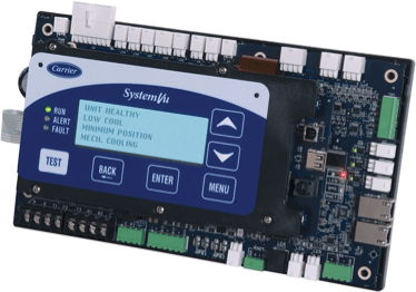
System Vu Controller Pt 2
Last month we introduced the SystemVu controller as a complete unit management system. It can be used as a stand-alone controller or as a fully communicating control, but there are a few setup procedures involved. When the unit is powered up, there is the initial start-up. If this is not completed, the SystemVu controller will continually display the initial startup prompt. The three things that need to be completed are the Quick Setup, Network Set, and the System Auto Test.
The Quick Setup includes common configurations like time, date, thermostat type, dirty filter timer, etc. Once this is completed, you have to set the Quick Setup Checklist to “done”, or it will continue to display that it needs to be completed. Network Setup is a submenu for specific network settings like CCN or BACnet. The SystemVu is defaulted to BACnet. When this is completed, make sure to set the Network Checklist to “done”.
During the setup process, the “service test function” is used to check compressors, heating, indoor and outdoor fans, power exhaust, economizer, crankcase heaters, and the alarm relay. This function is also used for troubleshooting the system in case there is an alarm or break down. To enter the service test function, press the TEST button on the SystemVu display at any time to access the Test menu. The service test mode is turned ON or OFF at the unit display. Once turned ON, other entries may be made with the SystemVu control. Service Mode Test will automatically turn off automatically, based on keypad inactivity or the test has completed and timed out. When using the service test function, operating limits for cooling, heating, and the economizer are ignored. Time guards for staging or delaying are limited to one minute.
System Auto Test when turned on will start with the Independent outputs, and this will turn components in the unit on and off. For example: crankcase heater, outdoor fans, indoor fan, etc. After testing these components, it then starts the cooling auto test, and then the heating auto test. Don’t forget, when this is completed, set to “done”. You will also be asked if you want the data entered into a service report.
When connecting the equipment to a thermostat, the SystemVu controller can interface with third party controls. When using a third party control, the control type has to be configured in the SystemVu controller. This configuration is only if the unit control type is a thermostat. There are four choices to choose from:
0 = CONV 2C2H – Conventional Thermostat 2 stage cool and 2 stage heat.
1 = DIGI 2C2H – Digital Thermostat 2 stage cool and 2 stage heat.
2 = CONV 3C2H – Conventional Thermostat 3 stage cool and 2 stage heat. This is the default setting.
3 = DIGI 3C2H – Digital Thermostat 3 stage cool and 2 stage heat.
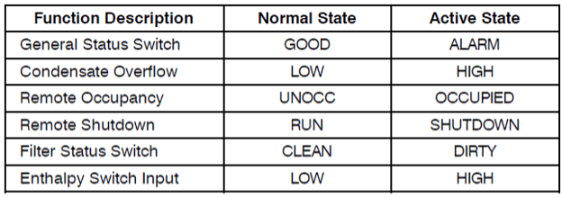
SystemVu also has optional configurable inputs. There are five physical board switch inputs (discrete inputs) and three physical board analog inputs. Here are inputs of each:
If troubleshooting is needed, the SystemVu Display shows the actual operating conditions of the unit while it is running. If there are alarms or there have been alarms, they will be displayed in either the active faults, active alerts, or the history alarm list. With an active alarm it will be indicated on the SystemVu Display by the Alarm Status lights. If it is an active alert, the yellow “ALERT” light will be lit. When faults are active, the red “FAULT” light will be lit. When there are no operational issues the green “RUN” light will be lit.
When troubleshooting the Cooling, Heating, VFD, or Economizer use the Systemvu display to view current alarms and alarm history for any faults to help direct you toward the problem.
As described above, this is just a brief description of what the SystemVu is capable of doing. You can see that SystemVu is a complete unit management system.
Sources:
48/50LC 07—26 Single Package Rooftop Units with SystemVu™ Controls Version 1.X Controls, Start–Up, Operation and Troubleshooting
48/50JC 04-06 Ultra High Efficiency Single Package Rooftop Units with SystemVu™ Controls Version 1.X Controls, Start-Up, Operation and Troubleshooting Instructions
More to explore
Updating Your SMAN/Testo Gauges
Some of you might have an older SMAN/Testo digital gauge. With the new refrigerants coming, you might need to update
How to Read a Ladder Diagram
Ladder diagrams, also known as ladder logic, are a type of electrical notation that illustrates how relays and electromechanical switches
Carrier VRF Static Pressure
All ducted VRF systems come from the factory set for 0” of static pressure. As we know from experience, this


