Updating Your SMAN/Testo Gauges
Some of you might have an older SMAN/Testo digital gauge. With the new refrigerants coming, you might need to update

Technical Services Manager
North Georgia District
You may have seen Code 69 while receiving a service call to a 25VNA8-24VNA9 2 thru 5 ton. Many times we get a call from a tech stating “I think I have a bad board, I just want to verify with you guys!” Many times it is a bad board; or is it?
Do a literature search In HVAC partners or your Carrier Service Tech App, for this system and find code 69.

Sure enough the literature is almost always right. The literature does state Inverter/compressor internal fault. As stated above, also stated is overcharged system, phase imbalance/compressor or inverter miswire, flooded start, inverter damage, or compressor damage. But if the compressor isn’t starting, then you can’t check the charge. So lets focus on the inverter and compressor for this discussion. Maybe we’ll all learn something new.
You start thinking maybe the inverter is bad, or maybe the compressor is bad. First you can confirm that the MOC board is good. Ohm out the MOC board across A and B , you should get a good reading between 27K and 32 K ohms. Also the DC voltage on A & B should be around 3 vdc depending on incoming line voltage to the unit.
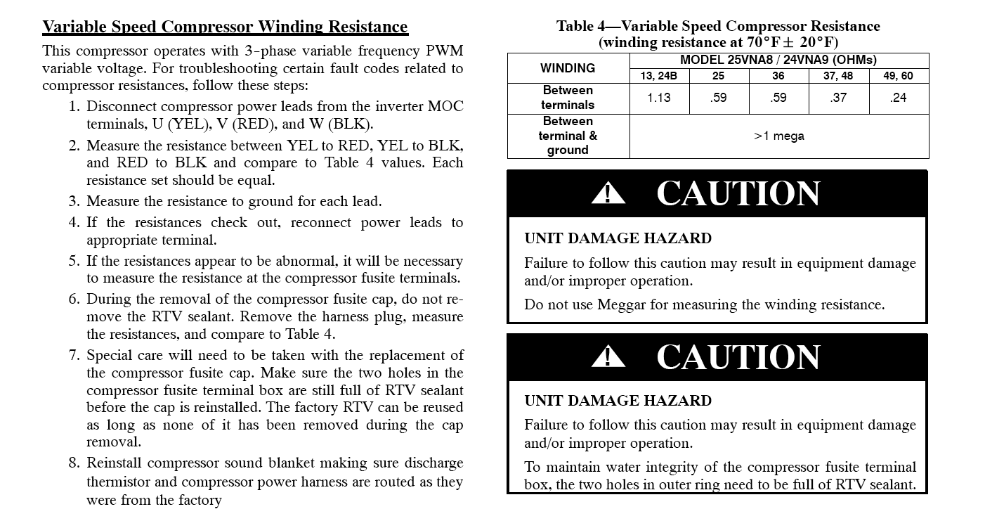
Then you ohm out the compressor wires from the inverter terminals U(YEL,), V (RES), and W (BLK). . You slide them off, ohm out and you begin getting some odd readings. You should get a stable, equal reading from the chart below, depending on which compressor tonnage you have. You should measure the resistance to ground from each lead. You shouldn’t get anything to ground.

You find the compressor resistance readings to be abnormal. Wow!! You begin to second guess your ohm/voltage meter. You change your batteries, or get a different meter. Having a very good workable meter is vital in this trade. So now you need to measure the resistance at the compressor fusite terminals. You will need to remove the sound barrier, a pain, but never the less, it must be done. During the removal of the compressor fusite cap, do not remove the RTV sealant. Remove the harness plug, measure the resistances, and compare to table 4. Once you remove the cap, you can measure the resistance at the compressor fusite terminals.. Recently, a tech removed the fusite cap, and found this:

If this tech had not removed the compressor sound blanket and removed the compressor fusite cap, he might not have found the melted power harness and melted compressor terminals. He probably would have believed the literature “inverter fault” and had to find this issue later. Then you have an upset customer because you didn’t go the extra mile and find the real issue.
So next time you get a service call, make sure and make the proper checks before making the final diagnosis.
So what have we learned with this lesson:
1. Always follow the fault codes when you get a service call
2. The fault codes are listed in the literature
3. Take a look at all the fault codes under the listed code before making the final diagnosis
4. Make sure you have a good working meter; and a backup meter is not a bad idea
5. Safety first. Before checking any inverter, cut off your disconnect and give the inverter capacitors time to discharge
6. Most of the information you will need to troubleshoot Carrier/Bryant systems will be located in HVAC Partners
7. Code 69 means Inverter/compressor internal fault
Disclaimer: The technical statements, information and recommendations contained herein are believed to be accurate as of the date hereof, but Mingledorff’s does not make representations or warranties, express or implied, as to its accuracy, its completeness, or the results to be obtained. The information is being provided for informational purposes only and is intended for use by persons having adequate skill and expertise regarding the proper selection, use and application of the products and recommendations and at their own risk and discretion.
Some of you might have an older SMAN/Testo digital gauge. With the new refrigerants coming, you might need to update
Ladder diagrams, also known as ladder logic, are a type of electrical notation that illustrates how relays and electromechanical switches
All ducted VRF systems come from the factory set for 0” of static pressure. As we know from experience, this
Keep up with the latest HVAC news from Mingledorff’s Inc.