Bubba Moore
Technical Services Manager
Southeast District
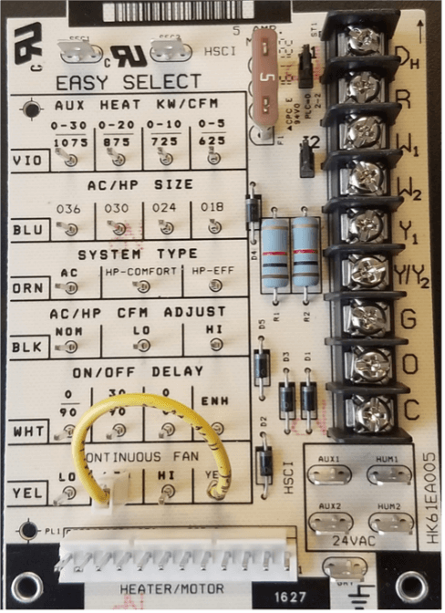
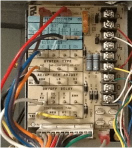
Easy Select Board in FV4 Fan Coils
The easy select board is used in the FV4 HVAC fan coil to configure the ECM motor to modify its operation to a pre−programmed table of airflows. The air flows are based on system size and mode of operation and will be modified from inputs, such as the need for dehumidification.

Now we will look at the 6 sections or modes of the easy select board. The Auxiliary Heat, section one, has a violet wire that comes from the wire harness. This would be placed on the pin that closely represents the electric heat package that is installed in the fan-coil. For example, if a 9 kw heat package was installed, the violet wire would be placed on pin 0-10, which would set the air flow for that electric heat package selected for the fan coil.
The AC/-HP Size, section two, has a blue wire that comes from the wire harness that would be placed on the pin that matches the outdoor unit tonnage. This will insure that the airflow delivered falls within proper range for the size of unit installed in all operational modes.
The System Type, section three, with an orange wire that comes from the wire harness would be placed on the pin for the type of system CFM needed, which would be selected from A/C, Heat Pump Comfort, or Heat Pump Efficiency. The A/C would provide 350 CFM per ton in heating and cooling. The HP- comfort would provide 315 CFM per ton in heating and 350 CFM per ton in cooling. The HP-efficiency would provide 350 CFM per ton in cooling and heating.

The AC/ HP CFM Adjust, section four, has a black wire that comes from the wire harness that is placed on the pin to adjust airflows to meet individual installation needs, such things as noise, comfort, and humidity removal. NOM or nominal follows the system type airflow. The LO reduces the nominal air flow by 10% of system type setting. The HI increases nominal airflow by 15% over system type setting.
The ON/OFF Delay, section five, has a white wire that comes from the wire harness that would be placed on the pin that meets the installation needs. The 0/90 is no on delay and 90 sec. off delay, the 0/0 is no on delay and no off delay, this is used for servicing the unit or when a thermostat is used to control the fan on off delay function. The 30/90 is a 30 sec. on delay and 90 sec. off delay, is used to allow system coils to heat up or cool down prior to air flow. This could help with cold blow in HP operation and enhance system efficiency. The enhanced has a 30 sec. on delay with no airflow followed by 150 sec. at 70% airflow with no off delay. The on/off delay is active only in cooling and heat pump only heating modes. In auxiliary heat mode or emergency heat mode, the ON delay is 0 seconds and the OFF delay is fixed and cannot be overridden.
The Continuous Fan, section six, has a yellow wire that comes from the wire harness which would be placed on the pin needed for the amount of air flow desired when using continuous fan. LO would provide 50% of high cool fan speed, Med would provide 65% of high cool fan speed but on the 006 models it would provide 71% of high cool fan speed, and HI would provide 100% of high cool fan speed. If you have a two−speed unit, do not select continuous fan as HI, because the low speed cooling will also run at HIGH airflow and insufficient dehumidification may result.
The easy select board can be configured to remove humidity by lowering the fan speed. This is done by connecting the DH terminal to a thermostat that can sense humidity and removing the J1 jumper on the board.
With these selections or modes set properly, the fan-coil will deliver the proper airflow for the system installed, help control humidity in the space, and make the space more comfortable.
The Easy Select board allows for the fan coil cfm’s to be configured for the installation needs and comfort of the customer.
Sources: Service and Maintenance Instructions SM-FANCOIL-07
More to explore
Updating Your SMAN/Testo Gauges
Some of you might have an older SMAN/Testo digital gauge. With the new refrigerants coming, you might need to update
How to Read a Ladder Diagram
Ladder diagrams, also known as ladder logic, are a type of electrical notation that illustrates how relays and electromechanical switches
Carrier VRF Static Pressure
All ducted VRF systems come from the factory set for 0” of static pressure. As we know from experience, this
HVAC Fan Coil
Keep up to date with the latest HVAC news from Mingledorff’s Inc.
